Output on a LCD
Comprehensive SPLC780D/HD44780 library
LCD Character Module | posted on Su, 13 Sep. 2015
Motivation behind this
To start with, I have a fascination for LCD’s, and second I want to give them good use for debugging. I “googled” a little bit for a library to use, the search result was poor because nothing seemed to be simple, complete and straightforward to use on PIC16 microcontrollers. Then I decided to take the weekend to make this. I intend my library to use the driver entire set of functions in such a way that is flexible and robust to allow debugging of other projects. These simple modules are the perfect start to explore the LCD world.
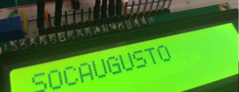
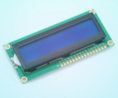
I want to use a display for debugging purposes mainly because to debug my PIC I either use the most rudimentary option which is LED’s, a special debug header (for my PIC16F690 I have one) or I can log to a PC using a terminal and the EUSART module. To debug it would be great to send tags from within the program and output them with alphanumeric characters, then the simplest option is to use a display with the SPLC780D controller (or similar), these are based on the Hitachi HD44780. Those modules have the same interface and perform the same functions. For example, I bought my 16x2 LCD module built on top of the SPLC780D driver. With these modules we will be able to write all the ASCII characters and create our own custom characters allowing us to easily and quickly output a text with information about the program, data acquisition or simply use as if it was a LED. Let's start building the library to output data and get a grasp of how this things work.
The basics of these controllers
Here you have another datasheet for the LCD module. I will not bother you with what you can read on the datasheet, but I want to point out that memory positions, timings for the instructions and sequences are very very important. I recommend you to pay special attention to datasheet page 39, 40, 46, 56 and 57.
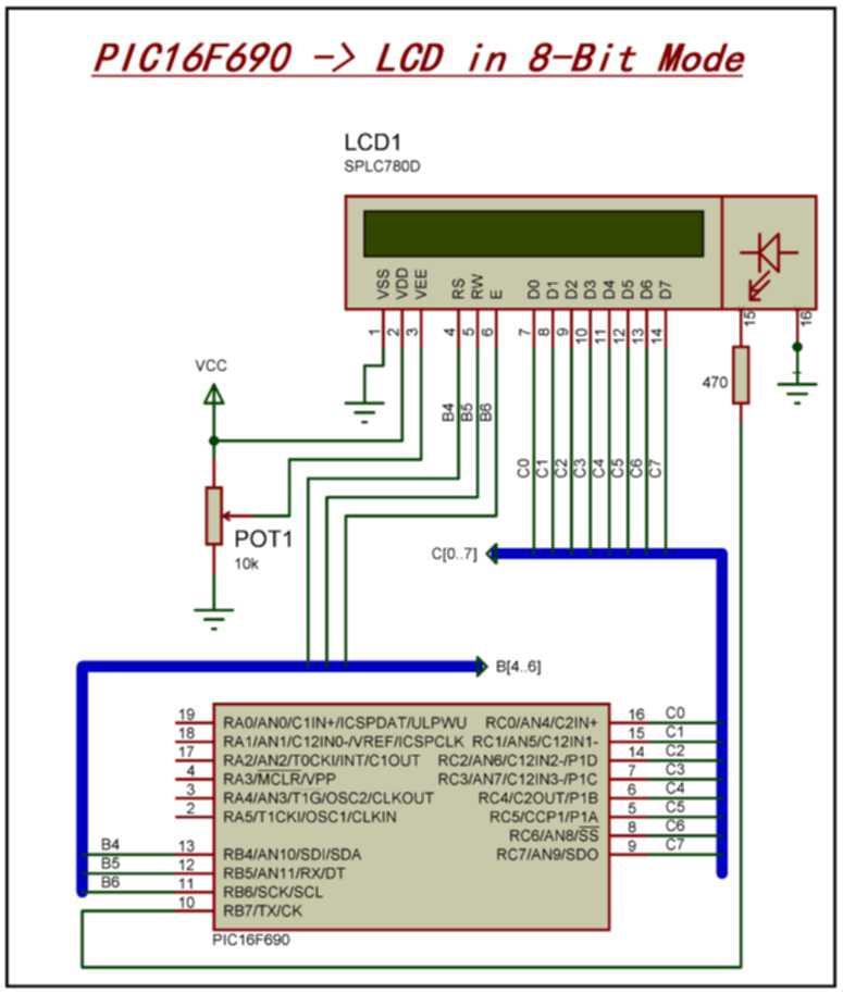
Module control is made using a 4-bit (4 lines) or 8-bit interface (8 line). I’ll focus on the 4-bit interface because then we only use one port with 8 I/O pins to control the functions of the LCD, nonetheless on the library you can choose to use the 8-bit mode. You're probably wondering why did I said that we need a complete port with 8 I/O's to control the LCD in 4-bit mode! Well, the 4 lines are to send data, so we need additional lines to tell the LCD to listen or to answer, as well as to save the information we send into its memory.
I was trying to avoid speaking in memory locations and types (because you can read it on the datasheet), but I think I cannot escape from it, otherwise it will be difficult to follow without reading the datasheet. The CGROM stores the native characters, by other words, how standard letters and numbers are drawn. We have then the DDRAM which is the memory that stores the information shown on the display at a given time. For example, if you write 0x30 (Zero in ASCII) in the position 0x00, you’ll have written in the first line, first character position the value zero (I’m considering the display is not shifted). Just for a quick reference, in a 2 line character LCD (see datasheet for other number of lines), the memories are arranged as follows:
- 1-line display (hex): 0x00 up to 0x27
- 2-line display (hex): 0x40 up to 0x67
The last memory space to talk about is the CGRAM, this is my favorite because we can create custom characters. I have to point out how small this memory really is. It only allows you to store 8 different characters, but you can change them as much as you want. Memory locations from 0x00 to 0x3F.
The displays typically have backlight (once I bought one that hadn't and I got really frustrated, I didn't know that was even possible), some have even RGB backlight. The library only supports simple backlight control, nothing fancy.
How to connect the display to your microcontroller
There are 16 pins on the display. As explained earlier, data can be sent using 8 lines in which pins DB0 to DB7 are used, or in alternative use 4 lines in which pins DB4 to DB7 are used. To control all the display functions from the microcontroller you will have to connect it as in the following pictures.
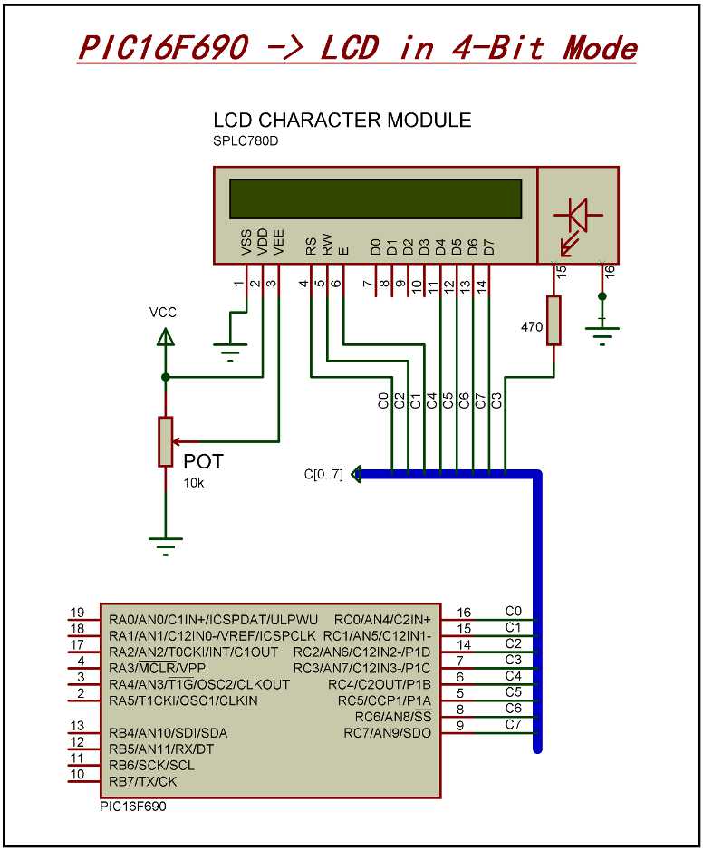
- VSS: Connect to GND
- VDD: Connect to the power rail that can be typically between 2.7V to 5V
- V0: You need a voltage divider or a PWM to control the contrast. I recommend a 10K pot.
- RS: Connect to the microcontroller
- RW: Connect to GND or the microcontroller
- E: Connect to the microcontroller
- A: Connect to VDD or the microcontroller. You will need a resistor in between to limit the current. A resistor around 470Ohm will do the job in safely to whatever voltage (up to VDD) you´re applying.
- K: Connect to GND.
- DB0-DB7: Connect to microcontroller (4-bit mode: DB4-DB7)
- Use the same voltage for the display and MCU.
- Adjust the contrast potentiometer if you don´t see nothing showing up.
- In 4-bit mode connect the display to either 0-3 or 4-7 I/O's. You cannot use for example 2-5.
- If you´re having problems, start by connecting the RW pin to GND and set the mode
#define pinRW_GNDon SPLC780D.h. - Connect the backlight to VCC (don´t forget the resistor in between!).
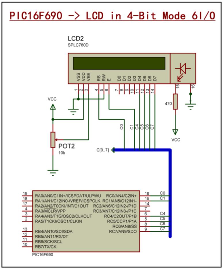
In the following picture I show you the minimum required I/O's to display your data. However with this configuration backlight control and read operations will not be available. If you're running low on available pins go for this solution.
Quick start method
If you're like me and want to see the LCD kicking as fast as you can you'll probably use this instructions. So follow the next steps:1. Connecting the LCD to the MCU
- Use the schematic above that only require 6 connections.
- Adjust the potentiometer to around 4.5V (I´m considering you´re using VDD=5V). In case this is too high, the LCD will have the pixels completely dark but at least you know it's working. Then lower the voltage level when you load the demo on the MCU (see ahead).
- Preferably use one demo board and one solderless breadboard to connect the LCD and the MCU. This is just to make your life easier.
2. Adjust the program configurations to your hardware
- Open the project in MPLAB. You will need HI-TECH toolsuite or Microchip XC8. The XC8 is free.
- Open the file SPLC780D Controller.mcp. And start by selecting the correct MCU that you're using.
- In the file main_SPLC780D.c adjust the config word. My config word to the PIC16F690 is
__CONFIG(FOSC_INTRCIO & WDTE_OFF & PWRTE_OFF & MCLRE_ON & CP_OFF & CPD_OFF & BOREN_OFF & IESO_OFF & FCMEN_OFF);
3. Modify the code to reflect your connections
In the file mcu_configuration.h you change what ports to use and the function of the I/O pins. So see my configuration below, I think is pretty easy to make changes:
#define dataPort	    PORTC
#define dataPortCnt	TRISC
#define controlPort	PORTC
#define controlPortCnt	    TRISC
#define pinRS			0
#define pinRW
#define pinE			1
#define pinBacklight
#define pinDB0
#define pinDB1
#define pinDB2
#define pinDB3
#define pinDB4			4
#define pinDB5			5
#define pinDB6			6
#define pinDB7			7
You can see that I'm using
PORTC for both control and data. Just don't forget that if you change PORTC to for example PORTB, you'll need to change TRISC to TRISB.
The pins that do not have any value will not be used. If you add values to the pins above you will also need to define its usage in the file splc780d.h.
4. Reflect the MCU configurations on the controller driver
To finish the configurations, go to the file splc780d.h and change the following:
//------LCD Configuration-----------//
// From each group only one option can be enabled //
//#define	dataLength_8
#define dataLength_4

//#define numberLines_1
#define numberLines_2

#define caracterFont_8
//#define caracterFont_11

//#define pinRW_IO
#define pinRW_GND

#define pinBacklight_VCC
//#define pinBacklight_IO

#define CHARACTERSNUMBER 16
On the configuration above I'm defining my LCD as having 16 characters and 2 lines. I'm also telling the driver to use 4-bit mode and to ignore the RW and backlight control pin.
5. Download the program and run the demo
- Download the program to the MCU
- Run the program and a demo should appear on the display, showing the entire set of functions implemented.
- Check the file main_splc780d.c if you want to use the library without explanation. Just copy and paste.
LCD Character Module
TAGS
LCD 16x2, SPLC780D, HD44780, LCD library, write to lcd, read from lcd, 4 bit lcd mode, 8 bit lcd mode