Output on a LCD
Comprehensive SPLC780D/HD44780 library
LCD Character Module | posted on Tu, 15 Sep. 2015
How is the library structured?
In the project files you will have the following files:
- main_SPLC780D.c and main_SPLC780D.h: These files contain the main (entry point) function and the demo.
- mcu_configuration.h: Where we adjust the hardware configuration of the program.
- splc780D.c and splc780D.h: Both are the main files of the library. The header file (.h) has the definitions and the source file (.c ) the functions.
The main_SPLC780D.* can be deleted when you insert this into your program. Those files are just for demonstration purposes. They are also intended to work as example of the entire set of functions implemented in the library. With them you can at least understand the sequence and how the functions can be used.
In the file mcu_configuration.h is where it begin the playground. The definition #define _XTAL_FREQ 4000000 is telling the compiler that all the delay functions should account with a MCU speed of 4MHz. The hardware specific setup is the next step. Once again use the #define declaration to#define dataPort PORTC and tell the compiler that you want to use the PORTC I/O pins to send the data into the display controller. The definition is made on the top of this file to avoid the need to go and change all the PORTC calls inside the library functions. When you change the definition here you’re changing everywhere. I’m using the following macros to set, reset and toggle I/O’s. There is one macro to read them too.
#define sbi(port,bitno) ((port)|=1UL<<(bitno)) // Set bit in port
#define cbi(port,bitno) ((port)&=~(1UL<<(bitno))) // Clear bit in port
#define tgl(var,bitno) ((var) ^= 1UL << (bitno)) // Toggle bit variable
#define tst(var,bitno) (((var)&(1UL<<(bitno)))>>(bitno)) // Test bit in variable
All the above macros are also listed in the file. To use this macros we write something like this:
tgl(PORTC,0). The previous code will toggle (set/reset) the I/O pin 0(zero) in PORTC.
PORTC to, let's say, PORTB you NEED also to modify the control register from TRISC to TRISB in this particular example. If you fail to do this, the tristate of the ports will not be properly defined and it will just not work.
Let’s see the I/O pins now. The pins not used, for example on the 4-bit mode, don’t need to be defined, however in the file splc780D.h if you define the library to use those pins the compiler will give you the appropriate error (I hope).
#define pinRS		0
#define pinRW		2
#define pinE		1
#define pinBacklight    3
#define pinDB0
#define pinDB1
#define pinDB2
#define pinDB3
#define pinDB4	        4
#define pinDB5	        5
#define pinDB6	        6
#define pinDB7	        7
The pins DB[0..7] need to be in the same port and need to be defined in sequence. For the 8-bit mode you need one I/O port with 8 pins. For the 4-bit mode, you can either use the lower or the higher nibble this means the pin DB4 can only be 0(zero) or 4(four). In the example above I’m using one port where all the pins are populated to send commands and data.
To conclude this small explanation of the library structure, let’s get into the file splc780D.h. This file is all about the display. All the function prototypes are declared in the top of the file. We are going to see each one in detail further ahead, but for reference I leave the list here:
void LcdWriteCmdByte(unsigned char data);
unsigned char LcdWriteDataByte(unsigned char data, unsigned char line, unsigned char pos);
unsigned char LcdReadDataByte(unsigned char * data, unsigned char line, unsigned char pos);
unsigned char LcdWriteNextDataByte(unsigned char data);
unsigned char LcdWriteCGRAMByte(unsigned char data, unsigned char chara, unsigned char pos);
unsigned char LcdReadCGRAMByte(unsigned char * data, unsigned char chara, unsigned char pos);
unsigned char LcdWriteCGRAMNextByte(unsigned char data);
unsigned char LcdSetLocation(unsigned char line, unsigned char pos);
unsigned char LcdSetCGRAMLocation(unsigned char chara, unsigned char pos);
void LcdGetLocation(unsigned char * line, unsigned char * pos, unsigned char * mode);
void LcdGetCGRAMLocation(unsigned char * chara, unsigned char * pos, unsigned char * mode);
unsigned char LcdCustomCharWrite(unsigned char customChar[], unsigned char sizeofChar,
unsigned char CGRAMadr,unsigned char line, unsigned char pos);
unsigned char LcdSetBacklight(unsigned char status);
void LcdDisplayClear(void);
void LcdReturnHome(void);
void LcdEntryMode(unsigned char increment, unsigned char shift);
unsigned char LcdCursorDisplayShiftRight(unsigned char displayShift);
unsigned char LcdCursorDisplayShiftLeft(unsigned char displayShift);
void LcdDisplayControl(unsigned char display, unsigned char cursor, unsigned char blink);
unsigned char LcdInit(unsigned char increment, unsigned char shift, unsigned char display, unsigned char cursor, unsigned char blink);
Following the prototypes are the LCD configurations. Starting by the definition of the communication mode. For the 4-bit mode you need to
#define dataLength_4 and comment //#define dataLength_8. In case you want to use 8-bit mode you need to reverse the comments://#define dataLength_4.
//#define dataLength_8
#define dataLength_4
Advancing to the LCD number of lines. With the same principle as for the communication mode,
#define and comment the appropriate lines. I defined my display with 2 lines:
//#define numberLines_1
#define numberLines_2
In some displays you can define the number of pixels for each character to be 5x11. However my display only alows for 5x8 and therefore the library was not tested with 5x11 characters. Use
#define caracterFont_8 to start with and then you can change for #define caracterFont_11 after the confirmation that all is working with 5x8. Let me know if you find any bug related with this definition. This is only used when drawing our own characters in the CGRAM.
This starts to be somewhat boring....everything is the same but anyway, let's go to the RW and backlight pin definition. If you choose to use the simple connection mode where the backlight is connected to VCC and the RW pin to the ground you shall set #define pinRW_GND and #define pinBacklight_VCC and comment //#define pinRW_IO and //#define pinBacklight_IO. Otherwise reverse the settings.
Finally the last setting, the number of characters. Actually this is not used, but I want to implement further improvements to the library. I want to implement shift control logics, this will allow the MCU to know what characters are shown and what is hidden in the display. This is possible because in smaller displays the memory size is bigger than the display size, so you can hide characters out of the visible memory positions and then shift the display to that location. I have defined 16 characters like this: #define CHARACTERSNUMBER 16.
For today that's all. I will post more in the next days. So check the next page for updates......
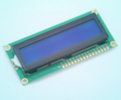
LCD Character Module
TAGS
LCD 16x2, SPLC780D, HD44780, LCD library, write to lcd, read from lcd, 4 bit lcd mode, 8 bit lcd mode