Wireless Communication
Basic RF link with Manchester Code
Basic RF Module | posted on We, 06 Jan. 2016
Introduction
I first wanted to start playing around with these modules after looking into a project on Hackaday.io, the project in question stated the ability of providing >95% communication success rate between these two modules using Hamming error correction. It was supposed that due to the simplicity of the transmitter code and effective error correction methods on the receiver it would allow a very low power transmission. I couldn’t achieve that (because I was stubborn and did not want to include a crystal, therefore the sync was not good enough), but because I already had bought the modules, I wanted to give them good use. From previous work I had good experience with Manchester Code with systems were the clock was not accurate, so let´s do exactly that on a PIC microcontroller.
Code to use in these simple RF links is very useful and can be even used in other modules with serial interface. However only effective code with high degree of reliability and predictability is actually valuable in some way. I would like to add that Manchester Code is a very common method in systems where the clock is not accurate.
Note that I will not extensively explain the basics of these RF links neither Manchester Code because this is already widely spread on the net and I would not add nothing. I will be focusing on the results which is what matters for the hobbyist. If you have an arduino this is not for you, but I recommend you to go HERE. For this article I'll use a Microchip PIC16F690.
RF Module Tech Specs
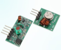
I should start by saying that these modules are unidirectional and the ones that I've bought are the 433Mhz version. The transmitter ref. is FS1000A and the receiver ref. is XD-RF-5V. I’ve welded a 433MHz helical antenna in each module. You can find these antennas in eBay using the search keyword “10pcs 433MHZ Helical Antenna”. The antennas should be soldered directly to the boards in the antenna hole in both RF modules.
- Frequency Range(MHz): 433MHz+/-6MHz
- Model: XL433M-T1
- Gain(dBi): 2.2
- Input Impedance(OHM): 50
- Max-power(dBm): 30
- Diameter(mm): 5
- Length(mm): 34+/-1
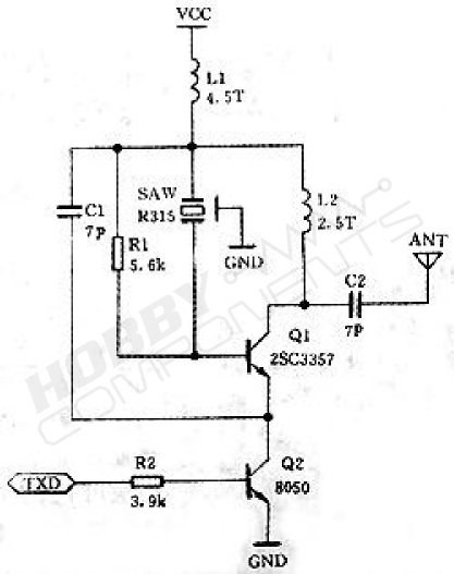
The transmitter is a small 22x21x8mm board where you need to weld the antennas and connectors (2,54mm spacing). There are several versions but the one I got has the transistors in a SOIC package. The schematic can be checked HERE.
- Emission Frequency (MHz): 433
- Model: FS1000A
- Operating Voltage (V): 3.5-12
- Quiescent Current (uA): >100
- Operating Current @3.3V (mA): 9 (measured)
- Operating Current @5V (mA): 13 (measured)
- Modulation: ASK/OOK
- Bit Rate (kB/s): 4
- Transmission Power @12V(mW): 25
- Frequency error (kHz): +150 (max)
- Dimensions(mm): 22x21x8
- Pinout (Front L->R): 1-DATA|2-VCC|3-GND
The receiver is a bit bigger with a 30x14x7mm board. You also need to weld the antennas and connectors (2,54mm spacing). Schematic to be seen HERE.
- Receiver Frequency (MHz): 433
- Model: XD-RF-5V
- Operating Voltage (V): 5
- Current Consumption (mA): 3,8 (measured)
- Modulation: ASK/OOK
- Receiver Sensitivity(dB): -105
- Dimensions(mm): 30x14x7
- Pinout (Front L->R): 1-VCC|2,3-DATA|4-GND
RF Module Performance
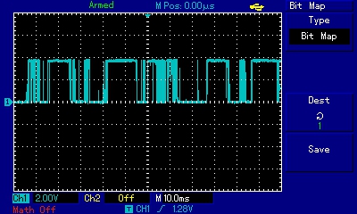
When the transmitter is on but with no data being fed into TX pin, the receiver only captures noise and is not sync with the transmitter, as shown in the picture below.
On the next picture, one push button was hooked to the transmitter data pin. Note that when the data pin state is changed, the receiver captures that signal, however if I keep sending a 1 signal the receiver will eventually return to a 0 value. On the picture, the blue line (CH1) is the transmitter data pin and the yellow line (CH2) is the receiver data.

Next up is sending a pulse train signal to the transmitter and see what is the maximum speed that we can actually achieve with this. We can see that a square pulse with a frequency of 2.46kHz has already a significant phase shift.
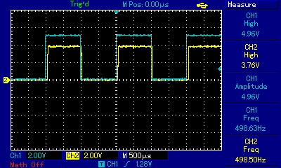
Pulse Frequency: 498Hz
In all these scopes the blue line (CH1) is reference and the yellow line (CH2) is the receiver signal. Even with such low frequency there is a significant ramp up time, but is not a show stopper.
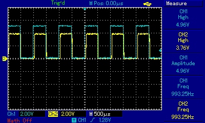
Pulse Frequency: 993Hz
My MCU is running with the internal clock and the frequency is not a beautiful round number, but it´s good enough for comparison. With a frequency of around 1kHz we´re still good to go.
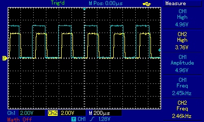
Pulse Frequency: 2.46kHz
We start to see a significant phase shift.
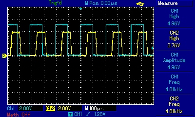
Pulse Frequency: 4.81kHz
At this frequency it's completely useless.
Now we will run some distance tests. These tests are not meant to be exaustive, I just want to have a rough idea in two or three different scenarios and check the behavior. Download on the right tab the program I used on the transmitter/receiver during the tests if you want to try to recreate them.
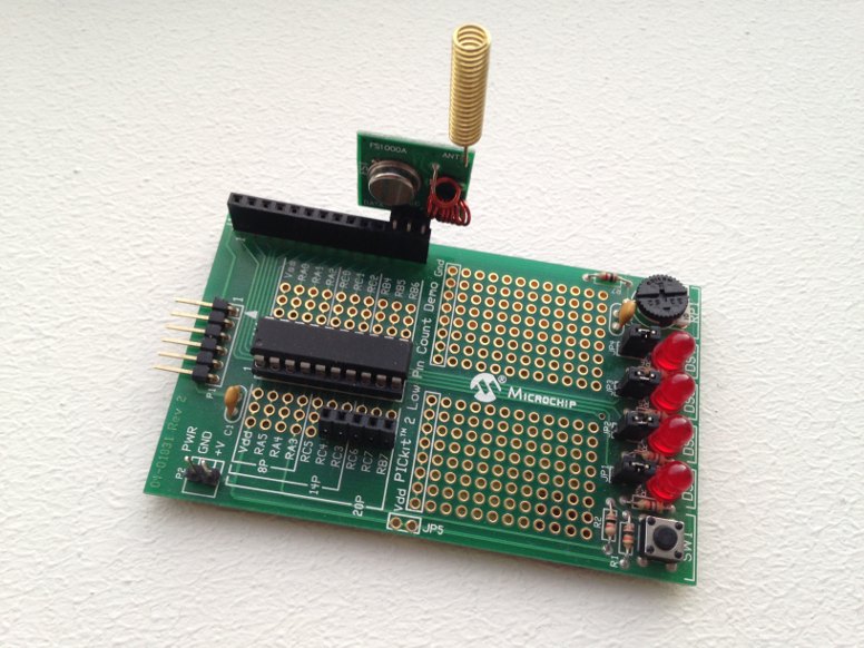
For the transmitter, I hooked it up to an old Microchip low pin count demo board that I´ve here. The button is being used to switch frequencies, between 500Hz and 4kHz in 500Hz steps. I connected the RF data pin to the microcontroller RC2 pin, but there is also a cloned output in RC3, this is useful to scope it with a oscilloscope in this board. The button is connected to the pin RA3 (note that it´s required a pull-up resistor).
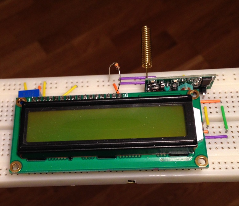
The receiver was assembled in a solderless breadboard. I used the LCD Library to display the number of faults measured by the test program. LCD is configured to be used in 4bits data mode, with the LCD RW pin tied to GND and the backlight (A) supplied by VCC through a 10k resistor. To make it work without modifying the program you need to use the LCD connections in a 4 bit mode (see HERE), but the MCU connection shall be the following
- pin RS - RA0
- pin E - RA1
- pin DB4 - RB4
- pin DB5 - RB5
- pin DB6 - RB6
- pin DB7 - RB7
- pin Data - RC5
The first test was done inside a building. The walls are made from wood (no reinforced steel) so they are relatively permeable to radio frequency waves. The emitter was supplied by 5Vdc and the frequencies varied between 500 and 4kHz. The result is very similar for the tested frequency range and no significant deviations were noted, in all cases a bit loss ratio of 100% was achieved at a range of 15m approximately (3 walls in between). With two walls in between the emitter and receiver and with a distance of 10m (approx.) the bit loss ratio is considerably lower, about 15%. As it´s expected, the range indoors is very limited and obstacles like walls, doors, cabinets, and others reduce substantially the signal strength.
Afterwards I went for a line of sight test outdoors, the weather was good and I was in the mood to play around with the RF modules. I went back and forth, up and down, changing the emitter height, going behind buildings, and this is what I discovered: First, the increased height (from 0 to 10m) improves slightly the range allowing 2 to 5% more distance between nodes. Second, if there is a barrier (reinforced concrete wall) between the nodes when the distance is bigger than 15m, the bit loss ratio is 100% immediately as we bend the corner. Lastly, I had a funny result in terms of range versus pulse train frequency. Somehow I manage to get increased distance (successful communication) for the 2kHz range, and I cannot explain that (and Yes I double checked). For frequencies between 500-1,5kHz and 3-4kHz, the 100% bit loss ratio was achieved at 40m, while for frequencies around 2kHz was just achieved after 67m. With line of sight the bit loss ration increases progressively but it´s curious that one step forwards or one step back it´s what it takes to have some received bits or don´t have it at all. 0% bit loss ratio is kept up to a distance of 15-18m.
Basic RF Module
TAGS
RF module, 433Mhz, Manchester Coding, PIC16F690
SOURCE CODE
Software Used: MPLAB IDE 8.73 + Hi-TECH C v9.81