Wireless Communication
Basic RF link with Manchester Code
Basic RF Module | posted on We, 06 Jan. 2016
Brief description of the transmitter code
The transmitter code is the easiest part of the communication system, so let´s start this project by going through this node first. To transmit data, it´s required to establish a fixed pulse rate to send the encoded information. The most effective way of defining a fixed time interval in which the MCU performs one function is by using interrupts, this way we can use the idle time to perform other functions, which avoids having to wait in a delay routine just wasting precious clock cycles. A timer will trigger an interrupt every time its counter is equal to one comparison register creating then a fixed beat to accurately time the bit transitions. And basically that´s it, the rest is just Manchester Coding logic.
Well, there is a little bit more to it than just a timer. The program is supposed to be flexible and simple to use, so it´s also incorporated in its guts, a simple (really simple) queue based on a circular buffer data structure. This means that the user inputs a vector into the transmitter main function and this information is stored in a buffer and made available to the program as it´s needed with first in first out (FIFO) method.
Be aware that, objectively this code is a platform to build upon more advanced features, and soon limitations will pop-up. One of the first limitations to be encountered right now is the buffer feed. For example, if the program is transmitting data it´s not possible to load more data into the buffer making it transmit continuously. Right now, the routine will need to end before adding/sending more packets.
How to use the transmitter code
It´s really simple to use this code. First of all, configure the hardware and choose one frequency to initialize the module. Attention should be paid when choosing the frequency, because the real transition frequency is double the transmit frequency, this is because within each bit period there is always a logic level transition. See this Atmel Application Note for more info. The function to initialize the manchester coding module is unsigned char mcInit(unsigned int freq);.
Next use the function unsigned char mcSend(unsigned char * sendByte, unsigned char noBytes); , this function has 2 inputs and one output. It outputs SUCCESS0 when the function was successfully executed, otherwise it´ll output ERROR0. The first function input is a pointer for an array with the data to be sent, followed by the number of bytes to be sent.
To finalize, add the function void mcInt(void); in the interrupt vector. Note that it´s required to be checked if the interrupt was caused by TIMERFLAG and this flag shall be cleared upon exit. Is user responsability to add this piece of code in the interrupt vector function. It´s highly recommended the IF statement to check the flag NOT to have preceding code. See the example below:
void interrupt tc_int(void)
{
	if(TIMERFLAG)			// No code before this line
	{						// To ensure proper timing
		mcInt();
		TIMERFLAG=CLEAR;
	}
}

void init(void)
{
	mcInit(2500);				// Init Manchester Coding
}
void main(void)
{
	init();

	// test code

		TRISA3=1;				// Pin RA3 set as input for button
		TRISA0=1;				// Pin RA0 set as input for pot
		ANS0=1;					// Pin RA0/ANS0 set as analog

		ADCON0=0b10000001;		// Right justified, VDD, AN0 channel, ADC on
		ADCON1=0b00110000;		// Frc clock
		unsigned char readout[] = {0,0};

	while(1) {


		if (!RA3)
		{
			GO_DONE=1;
			NOP();
			while(GO_DONE) {}
			readout[0]=ADRESH;
			readout[1]=	ADRESL;
			mcSend(readout,2);
			__delay_ms(1000);
		}

	}
}
}
The code above was implemented for a Microchip low pint count board with the transmitter data pin hooked to the MCU RC2.
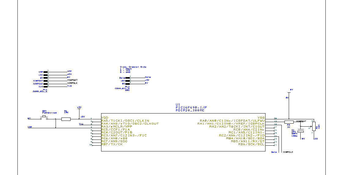
- Use the code on the right tab: Manchester Coding Transmitter.zip;
- Go to file configuration.h and change the port and pin to be used;
- If the frequency is changed, please update the
#define _XTAL_FREQinside configuration.h; - If other MCU rather than PIC16F690 is used, the registers must also be updated. Once again use the
#definestatements to update it; - Double check that the schematic used is the one above if the program on the right tab is to be used without modifications.
These are the fundamentals to start the transmitter. Let´s dig inside the receiver in the following page.
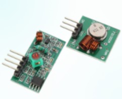
Basic RF Module
TAGS
RF module, 433Mhz, Manchester Coding, PIC16F690
SOURCE CODE
Software Used: MPLAB IDE 8.73 + Hi-TECH C v9.81