Wireless Communication
Basic RF link with Manchester Code
Basic RF Module | posted on We, 06 Jan. 2016
Brief description of the receiver code
The receiver is then the part of the system. In this project a timing method is used to capture the edges from the received data and synchronize the clock with the transmitter. Initially the transmitter must send a preamble of variable duration (according to the definitions in the transmitter program) and it´s mandatory to finish the preamble with the key 0xFE. The receiver will scan for received data until it receives the preamble and sync with the trigger key. Then the program will jump to the Manchester Decoding section where it will decode the incoming signals.
How to use the receiver code
To use the receiver code it´s required to initialize the hardware and internal registers, and that is done using unsigned char DecodingInit(unsigned char samples2pow, unsigned char attempts, unsigned char lockSamples); . The first parameter samples2pow it´s an exponential of base 2(the input values range is between 2 and 8) that defines the number of edge transitions from which the code shall try to reconstruct the transmitter clock. Be aware that the preamble size will play an important part here, because if the preamble is too short the code will never sync with the transmitter. The second parameter attempts is the number of times to try to sync to the clock in case of timing errors. Caution defining this value, a long loop (high number of attempts) to detect only errors will consume a lot of CPU time but will detect relevant incoming signals faster. Finally, the third and last parameter lockSamples is the number of samples (transmitter clock periods) to search for the trigger key 0xFE before giving up and return an error.
Next up is the interrupt code void mcInt(void) that shall be added immediately after the interrupt vector void interrupt tc_int(void). I recommend this to be the first line of code inside the interrupt function. An If statement can be used to check the cause of interrupt before the actual interrupt, if required.
Then it´s possible to receive data. For that the function unsigned char DecodingReceive(unsigned char numBytes); shall be used and the number of expected bytes to receive must be specified. If the number of bytes defined is higher then the number of valid received bytes, the code will return an error and clear the buffer.
To retrieve data the function unsigned char DecodingGetData(unsigned char i, unsigned char * data); is the one to be used. The first parameter is the data position in the receiver buffer (starting from index zero) and the second parameter is a pointer to a variable. The function will return error if the index is out-of-bounds. Below and example using and LCD to output the received data:
void interrupt tc_int(void)
{
	mcInt();		// Shall not have any code before
}
void main(void)
{
	#define DATASIZE 2

	DecodingInit(2,10,100);
	LcdInit(INCREMENT_MSK,OFF,DISPLAY_MSK,CURSOR_MSK,OFF);

	unsigned char data[DATASIZE] = {0}; 		// Read Data buffer
	unsigned int dataOut=0;

	const unsigned char msgDataOut[]= "ADC Value:";
	LcdSetLocation(1,0);
	for (unsigned char i=0; i<10 ; i++)
    {
    LcdWriteNextDataByte(msgDataOut[i]);
    }
    unsigned int msgNo=0;
    const unsigned char msgRecMsg[]="Message no.:" ;
    LcdSetLocation(2,0);
    for (unsigned char i=0; i<11 ; i++)
	{
		LcdWriteNextDataByte(msgRecMsg[i]);
	}
	while(1) {
		if(!DecodingReceive(DATASIZE))
		{
			for (unsigned char i=0; i<DATASIZE; i++)
			{
				DecodingGetData(i, &data[i]);
			}
			dataOut= ((data[0]<<8) & 0xFF00) | (data[1] & 0x00FF);
			msgNo++;
			LcdSetLocation(1,12);
			unsigned char str[4];
			sprintf(str, "%04d", dataOut);
			for (unsigned char i=0; i<4; i++)
			{
				LcdWriteNextDataByte(str[i]);
			}
			LcdSetLocation(2,12);
			sprintf(str, "%04d", msgNo);
			for (unsigned char i=0; i<4; i++)
			{
				LcdWriteNextDataByte(str[i]);
			}
		}
	}
}
The code above was implemented in a breadboard with the receiver data pin hooked to the MCU RC5/CCP1.
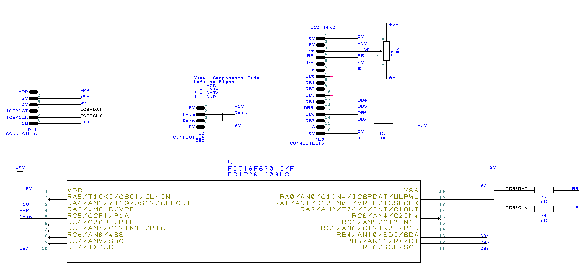
- Use the code on the right tab: Manchester Coding Receiver Timing.zip;
- Go to file configuration.h and change the port and pin to be used (go to the end of the file for LCD registers, the RF data pin shall be connected to the MCU CCP pin);
-
If the frequency is changed, please update the
#define _XTAL_FREQinside configuration.h; -
If other MCU rather than PIC16F690 is used, the registers must also be updated. Once again use the
#definestatements to update it; - Double check that the schematic used is the one above if the program on the right tab is to be used without modifications.
And that´s it, if everything was done properly you should have a robust communication system which is really cheap.
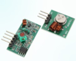
Basic RF Module
TAGS
RF module, 433Mhz, Manchester Coding, PIC16F690
SOURCE CODE
Software Used: MPLAB IDE 8.73 + Hi-TECH C v9.81